Arduino库教程-有线-Digital Potentiometer
AD5171 Digital Potentiometer
这个例子展示了如何控制一个模拟设备AD5171数字电位器,这个可以通过I2C串行同步协议进行通信。通过用Arduino's I2C Wire Library,数字电位计将通过64等级的电阻,实现LED亮度渐变。
I2C协议涉及使用两线发送和接收数据:串行时钟引脚(SCL),Arduino或者Genuino主控板在一个规律的时间间隔的脉冲,和一个串行数据引脚(SDA),两个设备之间发送的数据。如时钟线从低到高的变化(称为时钟脉冲的上升沿),一个比特的信息——将会按顺序组成一个特定设备的地址和一个命令或者数据——从板上通过SDA线传输到I2C设备。当这个信息被发送(一个字节接一个字节),直到主控板在SCL上产生时序前,被调用的设备执行请求并通过同样的线和同样的时钟发送返回它的数据(如果有必要)到板上。
因为12C协议允许每个功能的设备有它自己唯一的地址,当主设备和从设备轮流在一个线上沟通,用上处理器的两个引脚,你的Arduino或Genuino开发板是可以和很多设备交流的。
硬件要求
- Arduino or Genuino Board
- AD5171 数字电阻器
- LED
- 220 ohm 电阻
- 2 4.7k ohm 电阻
- 连接线
- 面包板
电路
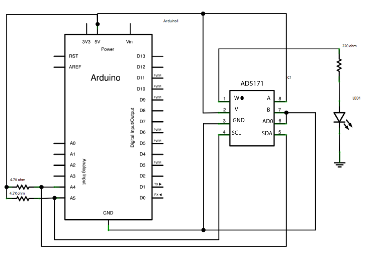
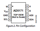
- 把 AD5171 的引脚3,6,和7,分别连到GND和引脚2和8 +5。
将数字电位器的引脚的时钟(SCL)pin4连到Arduino的模拟引脚pin5上,而数据线(SDA)pin5连到模拟引脚pin4上。两个SCL和SDA线都要加上拉电阻4.7K欧姆,并连接线+5V。
最后,把LED通过啊一个220 ohm的LED灯串联到AD5171的引脚1"wiper"。
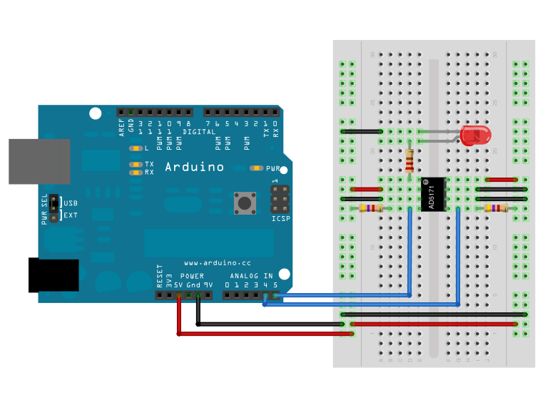
图由 Fritzing 软件绘制
当ad5171的引脚6“ADO”,连接到地面时,它的地址是44。添加另一个数字电位器到一样的SDA总线,连接第二个电位器的ADO引脚到+5V,这个可以改变它的地址为45。
你只能同时用两个数字电位器。
原理图
样例代码
// I2C Digital Potentiometer
// by Nicholas Zambetti <http://www.zambetti.com>
// and Shawn Bonkowski <http://people.interaction-ivrea.it/s.bonkowski/>

// Demonstrates use of the Wire library
// Controls AD5171 digital potentiometer via I2C/TWI

// Created 31 March 2006

// This example code is in the public domain.

// This example code is in the public domain.


#include <Wire.h>

void setup() {
  Wire.begin(); // join i2c bus (address optional for master)
}

byte val = 0;

void loop() {
  Wire.beginTransmission(44); // transmit to device #44 (0x2c)
  // device address is specified in datasheet
  Wire.write(byte(0x00));            // sends instruction byte
  Wire.write(val);             // sends potentiometer value byte
  Wire.endTransmission();     // stop transmitting

  val++;        // increment value
  if (val == 64) { // if reached 64th position (max)
    val = 0;    // start over from lowest value
  }
  delay(500);
}
[Get Code]
更多
- Wire.begin()
- Wire.beginTransmission()
- Wire.endTransmission()
- Wire.send()
- Wire Library – Wire库的参考网页.
- Digital Potentiometer: 控制一个模拟设备AD5171数字电位器。
- Master Reader/Slave Writer: 编程两个Arduino板之间通过I2C交流,另外一个设置为主读从写(Master Reader/Slave Sender)。
- Master Writer/Slave receiver:编程两个Arduino板之间通过I2C交流,另外一个设置为主写从收(Master Writer/Slave Receiver)。
- SFR Ranger Reader: 通过I2C读取超声波测距仪接口。
获取最新文章: 扫一扫右上角的二维码加入“创客智造”公众号
