Arduino内置教程-基本原理-模拟读取串口
这个例子展示怎样通过电位计从物理世界里读取模拟输入。电位计是一个简单的物理设备,在它的轴转动时可以提供一系列的阻值。流过的电压通过电位计和进入开发板的模拟输入口,可以测量由电位计产生的大量电阻,作为一个模拟值。在这个例子里,创建你的Arduino或者Genuino和你的电脑串口连接之后,运行Arduino IDE软件,你能监视这个电位计的状态。
硬件要求
- Arduino或者Genuino开发板
- 10kΩ电位计
电路图
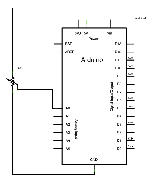
- 连接从电位计到你的开发板的3条线。第一根线从电位计的一个输出引脚到地。第二根从电位计的另一个输出引脚到5V。第三根从电位计中间的引脚到模拟引脚A0.
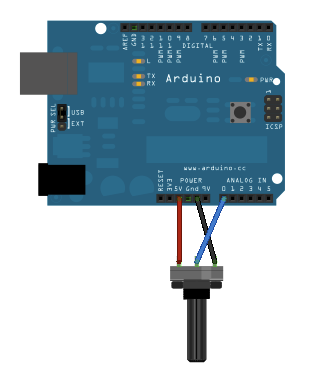
图片是用Fritzing制作的,更多电路例子参考Fritzing project page
通过旋转电位计的轴,你在刮器任意一个方向改变电阻的值(刮器连接到电位计中心引脚)。这个可以改变中间引脚的电压。当中心引脚和5v的电阻约为0时(中心引脚到地的电阻约为10kΩ),中心引脚的电压约为5V。当电阻被翻转时,中心引脚电压约为0,即是地。这个电压是你在读取输入引脚的模拟电压
Arduino和Genuino开发板有一个内置电路叫模拟到数字转换器,或者叫ADC,这个可以读取变化的电压,并转换成0到1023之间的数值。另外,analogRead()函数可以按比例转换一个0到1023之间的数字成为这个引脚上的电压。
原理图
样例代码
- 在下面的程序里,你只需要开始串口通讯,波特率为9600 bits。在你的开发板和电脑增加以下命令:
Serial.begin(9600);
- 然后,在你代码的主循环里,你需要创建一个变量来保存来自你的电位计的电阻值(这个数值在0到1023之间,最好用int):
int sensorValue = analogRead(A0);
- 最好,你需要打印这个信息到你的串口监视器窗口。你可以在代码的最后一行增加command Serial.println()来打印:
Serial.println(sensorValue)
- 现在,当你打开你在Arduino IDE软件上的串口监视器(可以通过键盘快捷键Ctrl+Shift+M打开),你应该看到和罐子位置相关的一个稳定的从0到1023的数据流。随着你转动电位计,这些数字会即时响应。
/*
  AnalogReadSerial
  Reads an analog input on pin 0, prints the result to the serial monitor.
  Graphical representation is available using serial plotter (Tools > Serial Plotter menu)
  Attach the center pin of a potentiometer to pin A0, and the outside pins to +5V and ground.

  This example code is in the public domain.
*/

// the setup routine runs once when you press reset:
void setup() {
  // initialize serial communication at 9600 bits per second:
  Serial.begin(9600);
}

// the loop routine runs over and over again forever:
void loop() {
  // read the input on analog pin 0:
  int sensorValue = analogRead(A0);
  // print out the value you read:
  Serial.println(sensorValue);
  delay(1);        // delay in between reads for stability
}
更多
- setup()
- loop()
- analogRead()
- int
- serial
- BareMinimum - 开始一个新程序的最简框架
- Blink - 使一个LED灯开关.
- DigitalReadSerial - 读取引脚,打印状态到Arduino串口监视器
- Fade - 示范用模拟输出使LED灯亮度变淡
获取最新文章: 扫一扫右上角的二维码加入“创客智造”公众号


